.
EMT 250 Painting by the Pop Artist Peter Max (courtesy Gary Ladinsky)
We’re sorry, but as of June 2017 we no longer service EMT equipment due to general unreliability of these models, time consuming issues in servicing them, and difficulty of delivery and pick up. For now we’ll continue to supply most of the parts for these models, and we’ll continue to offer our EMT 251 replacement color display and our program upgrade kits for the EMT 251 and 252. In some cases we may be able to offer limited phone support.
The EMT 250 and 251
Over the years, visitors to our shop were often surprised to see an “R2D2” –an EMT 250 or a 251– in the service area. Well, hardware reverbs weren’t always rackmount boxes with lights on the front! The history of studio reverb is fascinating, and EMT’s important developments in the field deserve special mention For decades the only way to create studio reverb was with an echo chamber. This was a special room with reflective surfaces, isolated from its surroundings, that contained one or more microphones and speakers. (Recording pioneer Bill Putnam is credited with building the first echo chamber in 1947 at Universal Audio, his studio in Chicago.
Good echo chambers were difficult and expensive to build, especially in urban locations where real estate was expensive and extensive sound isolation was needed to keep out traffic and other noises. Tape loops were sometimes used but they didn’t provide the random, complex reflections that were needed to replicate real reverb in an acoustic space. As for springs…well, they sounded like springs.

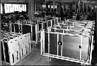
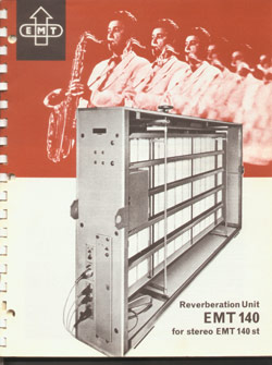
In 1957, EMT introduced the 140 Reverberation Unit. The 140 consisted of a large piece of sheet metal, suspended from a heavy steel frame. An electrical transducer (similar to a miniature speaker) transmitted sound energy to the plate, which along with its drive and pickup amplifiers, was built into a large wooden enclosure. The 140 was about 4 feet tall and 8 feet long, and weighed about 600 pounds. A damping plate, controlled by a servo motor, allowed adjustment of the reverb time. Though it was much smaller than an echo chamber it was still sensitive to ambient noise, and had to be kept in an isolated space. Still, the “plate” was a great advance. Instead of building 8 echo chambers, a large facility could put 8 140’s in a small iso room. It was the first cost effective answer for smaller studios, where actual chambers were not feasible.
EMT 140’s didn’t sound exactly like a real room but they sounded very good, and remained the most popular studio reverb for many years. The early ones used tube electronics, but in the 70’s EMT began shipping them with transistor circuitry.
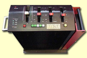
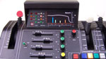
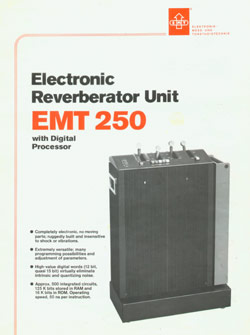
In 1972, EMT released the very first digital reverb, the rack mount 144. The capabilities of this early unit were limited, and few survive. But just four years later, EMT blew a lot of minds by introducing the 250 Electronic Reverberator Unit. It looked like something from an UFO, and sounded fabulous. A free standing unit, it was three feet tall with black “radiator” heat sinks on three sides and a large, bright red power supply assembly. On the upper control panel, 4 oversize levers resembling aircraft controls adjusted main delay/decay time, LF and HF decay times, and added delay to the send. The software also included delay, phasing, chorus, slap, and “space echo” programs. It had one input and either 2 or 4 outputs, depending on the version ordered.
Despite it’s early 12 bit architecture, the 250 had a beautiful sound. Its design was a joint effort between EMT’s engineers in Germany, Peter Bermes, also in Germany, and a small firm in Massachusetts called Dynatron. EMT designed the converters, I/O, and power supply, while Dynatron designed the main digital/processor board. The Dynatron effort was led by Dr. Barry Blesser, then a professor at MIT (and later an AES President).
Peter Bermes recalls that the 250 project utilized the most professional crew that he ever worked with. The brainstorming process involved 9 people seated at a round table, designing the EMT 250 from a scratch idea to a true product, including every aspect of design, development, marketing, choice of electronic elements, etc. The initial planning meeting required just 4 hours of hard thought and discussion, and took place on a very hot day in spring 1974, at the EMT plant in Kippenheim. Among the group were Erich Vogl, Karl Bäder, Barry Blesser and Peter Bermes. Mr. Bermes was conceived of splitting the electronic components into “hot and cold” elements. The hot elements were separated, given a vertical chimney profile, and painted red.
The finished unit had nearly 500 IC’s, and 3 cooling fans. To protect its revolutionary design, the part numbers and identification were scratched off most of the IC’s on the digital board. It utilized a memory board that held 80 “2102” IC’s — a popular 1k (!) static RAM chip that was also used in Radio Shack’s TRS-80, the first popular home computer. In accordance with Moore’s Law (which predicted the doubling of transistor density every year) later models used a RAM board with just 32 IC’s. The new board used the 4044, a 4K RAM chip. About 250 250’s were built, and they sold for about $20,000 each. I’m not sure whether EMT recouped their investment, but the machine was a huge milestone that heralded the dawn of digital audio in the recording industry.
Four years later EMT released the 16-bit 251. Along with a new reverb program and an LCD display, the 251 had extended frequency response, more parameter controls, more programs, and a remote control port — all in the same striking “sci-fi” package.
The EMT digital reverbs were something else. They were “Manhattan projects”, the result of intense efforts in a short period of time. Despite their high costs they were very successful, and remain one of the few digital technologies that stand the test of time, for one simple reason — the sound.
Though just a few hundred of these old girls were produced, it seems a safe bet that most units are still floating around — who would dispose of such an amazing looking machine? But as 250’s and 251’s pass the four decade mark, the attrition rate has caught up. Power supply problems, failed capacitors, aging ribbon cables, sluggish fans, dying RAM chips…those R2D2’s can develop a lot of problems. Fortunately, they are all fixable and repair is well worthwhile.
Reverberation System
Getting set up to service EMT’s wasn’t easy. They have about 500 IC’s, and on the main digital boards all the part numbers were sanded off in manufacturing. The 250 and 251 manuals include the power supply, converter, and analog schematics, the complex digital circuits were always kept under wraps by EMT and Gotham, the U.S. distributor. But by jumping through hoops some years ago we managed to acquire complete documentation for these units, and have tracked down all the RAM, shift register, and other obsolete IC’s. Since 1990 a steady stream of 250’s and 251’s have shown up and we’ve successfully brought them all back to life.
There was just one little problem… On 251’s, those custom LCD display became an Achilles heel. Near all have failed over the years, some quite dramatically. In Germany, Barco (who bought EMT in 1989) had no spares, but one of the engineers kindly gave us the original specs for the display, which mentioned that were made by Crystaloid Technologies in Hudson, Ohio. I contacted Crystaloid, told them the story, and a sales person got back to me quickly. Amazingly, they still had the original EMT specs on file and before I knew it, I was holding a price quote for a brand new batch of displays. Perfect, right?
Well, no. Crystaloid Technologies sent me another fax just a few weeks later. Victims of a changing economy, they wrote, a decision had been made that they’d soon be suspending operations, and closing entirely. They were very sorry but no new orders could be accepted
Electronic component manufacturing in the U.S. was losing ground to the Pacific Rim. Most small LCD displays like this one now came from China, Korea, and Taiwan. I Googled a dozen or so Asian firms, then sent them specs and RFQ’s, but with no success. Crystaloid still had the old dies and materials on hand, but the new guys in Asia were making better newer displays that weren’t compatible, or even close, to the original part. A newer display could be adapted, but a relatively complex PCB would be have to be retrofitted inside the housing. Sadly, the small number of displays I wanted couldn’t justify the R&D time and start up costs.
The EMT 251 Color Display was born— Fast forward to 2009 and enter Doug Jane, EE extraordinaire. An extremely talented audio designer in New Zealand, Doug had been collaborating and exchanging tips with me for many years. He serviced AMS and Eventide gear, and possessed a deep understanding of analog and digital circuit design. In early 2009, Doug told me that he had an EMT 251 with a dead display, and he was considering a retrofit solution. It had been years since I’d abandoned the project –– the disease had progressed and by now, nearly every 251 out there had a dead or dying display. Doug plunged into the project and the next thing I knew, sent photos of the first completed unit. He had incorporated two big improvements –– the display was now color, and resolution was much higher. The echo bars are displayed in different colors, making screen images easier to recognize at a glance. As a bonus, you could upload your own image for the background screen. the unit works with the original EMT 251 software and the revised software with the additional 250 reverb program.
Installation is fairly simple and can be done by anyone with with basic tech skills, the illustrated 10 page manual gives clear, step by step instructions. You take off the top assembly, remove the old display, and unsolder two wires. The PCB is removed and the new PCB and display are installed, using a cable adapter. Now four DIP switches are set –– three select the display timeout mode and the fourth selects “250 or non 250” software. The top assembly is reinstalled, and you’re done!
The EMT 251 Color Display
The EMT 251 color display complete kit and printed manual is $975 plus shipping.![]()
If you’re an 251 owner in Southern California and you’d rather that we do the upgrade, it’s not a problem. The install, including a general check out and calibration, is about $275. For more information, please contact us.
We’re very glad that we can finally offer this solution to EMT 251 owners.
Frequently Asked Questions – EMT 250/251/252
You guys sell a 251 upgrade kit that adds the 250 reverb program. If I install it, will my unit really sound like a 250?
As many people know, the EMT 251 was released with different programs than the 250, the similar unit that proceeded it. The 251 reverb has less low end and sounds less rich than the 250 version. At the time, EMT’s engineers must have felt that the 251 reverb was an
improvement, but early on, the 250 version proved the clear winner. In the 80’s EMT addressed this by releasing an EPROM upgrade that added the 250 reverb
to the 251 program set and ever since then, people have debated how closely they match. Though the converters are similar, 250’s were 12 bit , while 251 were 16. But it can get very fuzzy because vintage pieces age differently. Two sequentially numbered 250’s, side by side in a room, will have audible differences. Still, we’ve done side by side A–B tests, and believe that a working and upgraded 251 sounds as close to a 250 as another 250 –– if not perfect, very very good!
EMT 251 Owner’s Manual
EMT 251 Owner’s Manual
Yes! The 250 and 251 use an unusual fan made by Papst that was completely unavailable for many years, but we now stock replacements. To purchase, please go to our online store and search for the SKU EMT.fan. (Please note that even when these units were new, the fans were not completely silent — you’ll hear them if the unit is in your control room.)m.
The switches and switch caps are discontinued, but we have a small number of spares for in house repairs. Replacement lamps are still available.
Do any of these models have stereo inputs?
And why do some units have 4 outputs — was that for quad? All 250’s and 251’s one just one input. With the 250, the optional III and IV outs give a sort of 3-D effect and while the algorithm does not really treat them as “rear” channels, they can work as surround channels. The 251 has similar output mapping, but it adds C (reflection cluster) and P (panorama) to the front panel controls. While not the most intuitive functions, these outputs certainly broaden your range of sounds. A 251 with the 250 upgrade will have the same controls and parameters as a 250, when the 250 program is selected.
What about all the other EMT products?
EMT made many other interesting pro audio products including the EMT 156, EMT 244, EMT 248, EMT 257, EMT 250, EMT 251, EMT 258, EMT 259, EMT 260, EMT 261, EMT 266, and EMT 444.
Some Good EMT Links:
The History of EMT
Universal Audio Webzine – The EMT 250 Electronic Reverberator
Deutsch Perfektion – The History Of The Legendary EMT Turntables

A portion of the original 250 design detail (courtesy Peter Bermes)
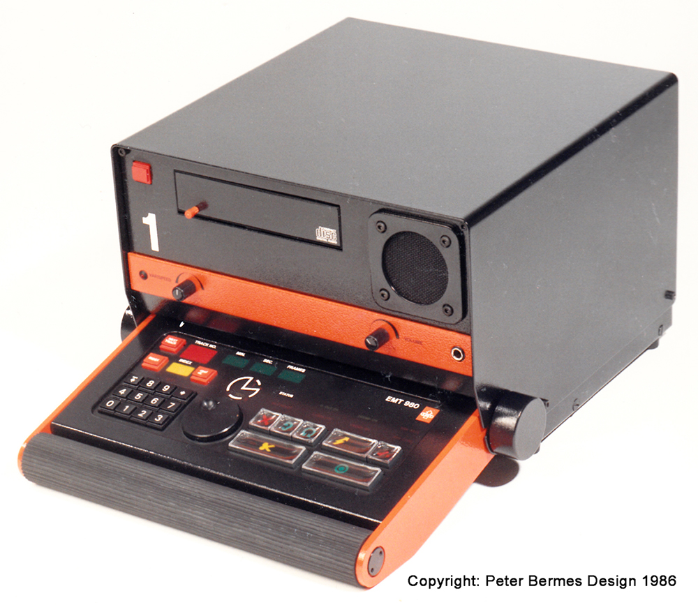
Early Prototype EMT CD Player (courtesy Peter Bermes)